In the highly technical field of water purification and fluid filtration, activated carbon serves as the primary barrier against volatile organic compounds (VOCs), free chlorine, halogens, and offensive organoleptic properties (taste and odor). When designing or maintaining residential, commercial, or industrial reverse osmosis (RO) systems, engineers must meticulously select the correct sequence of pre-filtration. A frequent point of technical confusion for assembly plants and water treatment professionals lies in understanding the exact difference between CTO and UDF filter cartridges. While both utilize the adsorption capabilities of activated carbon, their physical structures, manufacturing processes, fluid dynamic profiles, and placement within a filtration sequence vary drastically.
From our experience at HENGTENG Machine, having designed and supplied advanced filter production machinery to the global market for over three decades, identifying the functional difference between CTO and UDF filter mechanics is critical. Failing to recognize the difference between CTO and UDF filter performance parameters can lead to premature membrane fouling, excessive pressure drops, and catastrophic system bypass. In this authoritative guide, we will analyze the engineering mechanics of both filter types, explain their distinct manufacturing processes, and outline how to optimize your filtration production lines for maximum efficiency.
Table of Contents
1. The Engineering Mechanics of UDF Filters
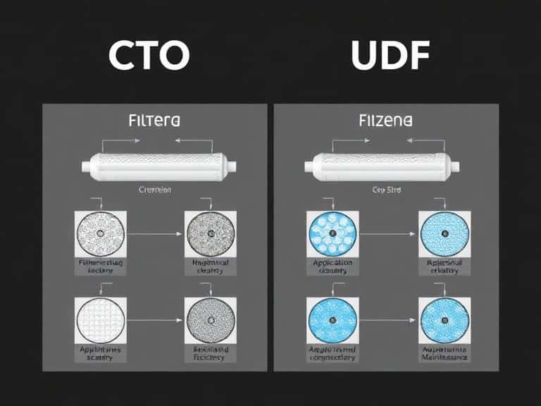
UDF stands for Ultra-fine Depth Filtration, though in the water treatment industry, it is universally recognized as the Granular Activated Carbon (GAC) filter. To understand the difference between CTO and UDF filter systems, one must first look at the physical state of the carbon within the UDF cartridge.
A UDF filter is constructed using a rigid outer polymer shell, typically manufactured from food-grade polypropylene. Inside this shell, loose granules of activated carbon (often derived from coconut shell, bituminous coal, or wood) are packed tightly. Because the carbon is in a granular, unbound state, the water flows through the interstitial spaces between the granules. This design offers a tremendously high surface area for adsorption. As water navigates through the loose bed of carbon, van der Waals forces draw chemical contaminants into the microscopic pores of the carbon granules.
However, the granular nature of the UDF introduces fluid dynamic challenges. Over time, water follows the path of least resistance, which can lead to a phenomenon known as “channeling.” When channeling occurs, water carves a direct tunnel through the carbon bed, bypassing the bulk of the filtration media and reducing contact time. To prevent this and ensure structural integrity, the assembly of these filters requires precision equipment. We recommend utilizing our proprietary UDF PP Filter Making Machine, which ensures optimal granular packing density, precisely ultrasonic-welds the end caps to prevent fluid bypass, and integrates necessary pre- and post-filter spun pads to contain loose carbon fines.
2. The Engineering Mechanics of CTO Filters
CTO stands for Chlorine, Taste, and Odor. In technical terminology, a CTO filter is a Carbon Block filter. Examining the construction of this filter highlights the fundamental difference between CTO and UDF filter technologies. Instead of loose granules, a CTO filter is manufactured by combining fine activated carbon powder with a thermoplastic polymeric binder (such as Ultra-High Molecular Weight Polyethylene, or UHMWPE).
Under specific thermodynamic conditions involving high heat and pressure, this mixture is extruded or compression-molded into a solid, porous block. This manufacturing process creates a uniform, tortuous path for the water to navigate. The solid matrix eliminates the channeling effect completely. Furthermore, because the carbon particles are milled to a much finer micron size than UDF granules, the CTO filter provides dual-action filtration: it performs high-efficiency chemical adsorption while simultaneously acting as a mechanical depth filter, trapping fine particulate matter (usually down to 5 microns or even 1 micron) on its exterior surface.
Producing a high-quality carbon block without restricting fluid flow requires exacting temperature control and binder distribution. From our experience, inconsistencies in the extrusion process lead to brittle blocks or excessive pressure drops. Our advanced CTO Carbon Block Filter Making Machine utilizes state-of-the-art thermal regulation and precision extrusion dies to guarantee a uniform pore structure, maximizing the active surface area while maintaining structural rigidity.
3. Analyzing the Core difference between CTO and UDF filter
When designing a multi-stage Reverse Osmosis (RO) system, engineers do not choose one filter over the other; rather, they utilize both in a specific sequence. Understanding the difference between CTO and UDF filter characteristics is what dictates this sequence.
Physical Structure and Fluid Dynamics
The most obvious difference between CTO and UDF filter units is their physical state—loose granules versus a solid block. Because UDF features loose granules, it inherently offers less resistance to water flow. This results in a lower pressure drop (Delta P) across the filter housing. Water can pass through rapidly, making the UDF filter excellent for the bulk removal of heavy chlorine concentrations. Conversely, the solid matrix of the CTO filter creates significant flow resistance, resulting in a higher pressure drop. The water is forced through microscopic pores, guaranteeing intimate contact with the carbon.
Adsorption Kinetics and Channeling
A critical difference between CTO and UDF filter reliability over time involves channeling. As previously mentioned, UDF filters are susceptible to channeling if subjected to high-velocity water surges. Once a channel forms, the filtration efficiency drops drastically. The CTO filter, being a solid block, is physically immune to channeling. Every drop of water is forced through the dense carbon matrix, ensuring uniform chemical reduction throughout the lifespan of the cartridge.
Placement in the Filtration Sequence
The operational difference between CTO and UDF filter mechanisms dictates their standard placement in a traditional 5-stage RO system. The standard sequence relies on three pre-filters before the RO membrane:
- Stage 1: PP Melt-blown Filter. Removes large suspended solids, dirt, and rust.
- Stage 2: UDF (Granular Activated Carbon). Handles the initial, heavy chemical load, absorbing the bulk of the chlorine. However, the loose granules generate fine carbon dust (carbon fines) due to internal friction caused by water flow.
- Stage 3: CTO (Carbon Block). This is the polishing pre-filter. A vital difference between CTO and UDF filter function here is that the CTO acts as a physical barrier. It catches the carbon fines shed by the UDF filter and performs a final, high-efficiency chemical adsorption to ensure absolutely zero chlorine reaches the delicate polyamide RO membrane (which would be instantly destroyed by chlorine oxidation).
4. Equipment, Manufacturing, and Quality Control
HENGTENG Machine, established in 1989, stands as a premier manufacturer of filter cartridge making machines in China. We understand that the ultimate performance of water filtration systems relies entirely on the precision of the manufacturing equipment. Our highly skilled engineering team has developed comprehensive production lines tailored to the unique thermodynamic and mechanical requirements of both filter types.
To successfully navigate the manufacturing difference between CTO and UDF filter lines, a factory requires specialized, dedicated machinery. For the UDF production, precise volumetric filling and ultrasonic cap welding are non-negotiable to prevent fluid bypass. For CTO production, uniform binder melting and consistent extrusion pressure are required to maintain a specific micron rating. We proudly supply both the UDF PP Filter Making Machine and the CTO Carbon Block Filter Making Machine to global manufacturers, ensuring compliance with strict international water quality standards.
Furthermore, to complete the pre-filtration production triad, we highly recommend integrating our 2e2mPP Melt-blown Filter Cartridge Machine. This equipment produces the vital Stage 1 sediment filters. Our 2-extruder, 2-mold (2e2m) system creates a gradient density structure in the PP filter, providing superior dirt-holding capacity and protecting the downstream UDF and CTO filters from premature clogging. Our commitment to quality is reflected in our ISO9001 and CE certifications and our efficient support system, ensuring our clients receive exceptional service from production to installation.
5. Summary Table: CTO vs. UDF
To provide a clear engineering overview, the following table summarizes the primary difference between CTO and UDF filter characteristics.
| Filter Characteristic | UDF Filter (Granular Activated Carbon) | CTO Filter (Carbon Block) |
|---|---|---|
| Physical Structure | Loose carbon granules inside a polymer shell | Solid, extruded or compressed carbon matrix |
| Pressure Drop (Delta P) | Low resistance, minimal pressure drop | High resistance, significant pressure drop |
| Filtration Mechanism | Chemical adsorption only | Chemical adsorption AND mechanical depth filtration |
| Channeling Risk | High risk over time or under pressure surges | Zero risk (solid matrix prevents bypass) |
| RO System Placement | Typically Stage 2 (Bulk Chlorine Removal) | Typically Stage 3 (Polishing and Fine Filtration) |
| Carbon Fines Shedding | High (requires flushing upon installation) | Extremely Low (traps its own and upstream fines) |
6. Frequently Asked Questions (FAQs)
Can I replace a CTO filter with a second UDF filter to improve water flow?
From our experience, we strictly advise against this practice in RO systems. The primary difference between CTO and UDF filter functionality is the CTO’s ability to trap carbon fines. If you use two UDF filters, the loose carbon dust generated by the granules will flow directly into the RO membrane, causing catastrophic and irreversible membrane fouling.
What causes the pressure drop difference between CTO and UDF filter types?
The difference between CTO and UDF filter pressure drop profiles is entirely structural. The CTO filter utilizes a thermoplastic binder to fuse microporous carbon powder into a solid block, resulting in a micron rating often around 5 microns. Water must force its way through this dense material. UDF features large, loose granules with massive interstitial gaps, offering little physical resistance to the water pressure.
How does manufacturing equipment impact the difference between CTO and UDF filter quality?
Manufacturing tolerances dictate filter efficacy. For a CTO block, if the extrusion temperature is too high, the polymer binder will melt completely and seal the pores of the activated carbon, destroying its adsorption capacity. HENGTENG Machine’s equipment utilizes precision thermodynamic sensors to guarantee optimal binder distribution without compromising the carbon’s microporosity.
7. Industry References
To further understand the regulations, testing methodologies, and scientific literature regarding activated carbon water filtration, we recommend consulting the following authoritative bodies: